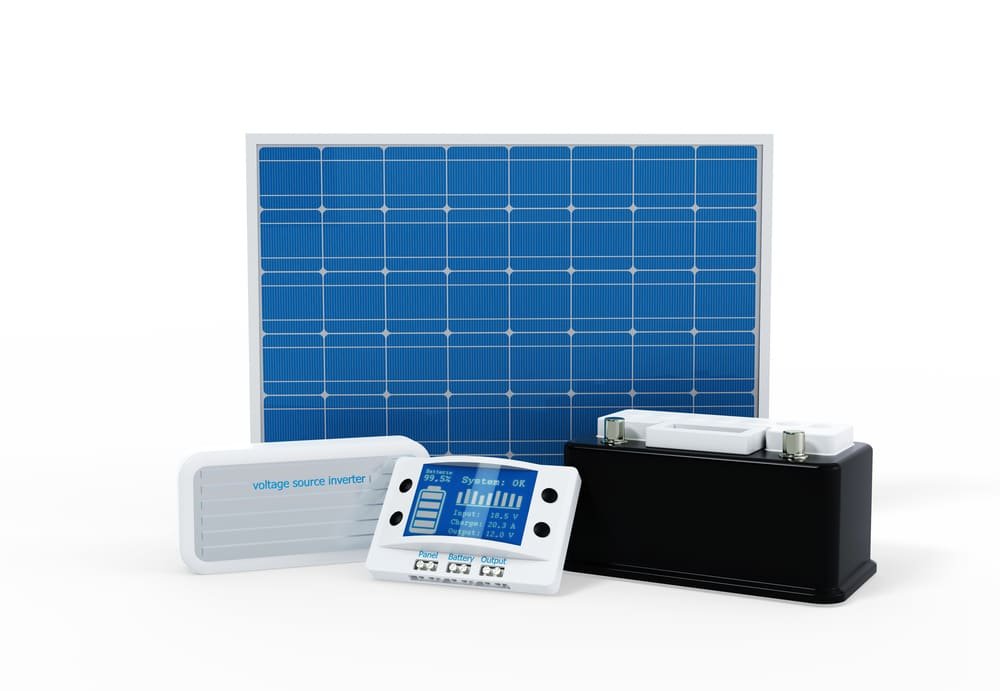
SOLAR CHARGE REGULATOR
Autonomous or Isolated Photovoltaic Installations need a system of batteries or accumulators to store the energy produced in surplus when we have the Sun and use it later when the panels are not capable of producing the necessary energy that the installation demands.
SOLAR CHARGE REGULATOR
The control of this process of charging and discharging the batteries is carried out by a device called “Charge Regulator”. This device, despite its simplicity and low cost, compared to the total cost of the installation, is essential to protect the useful life of the batteries and improve the operation of the photovoltaic system.
In theory it controls the charging and discharging of the batteries, better said, that there is no overcharging or overdischarging of the batteries thus increasing their useful life, although in actual practice, as we will see later, it only controls the charge, hence charge controller name.
Theoretical Scheme:
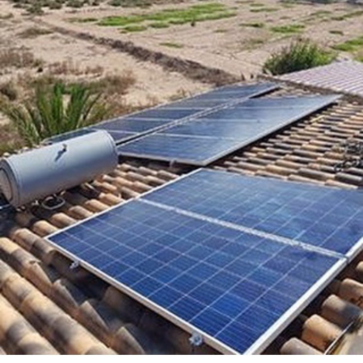
Photovoltaic installation
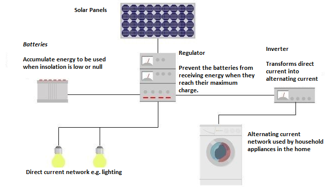
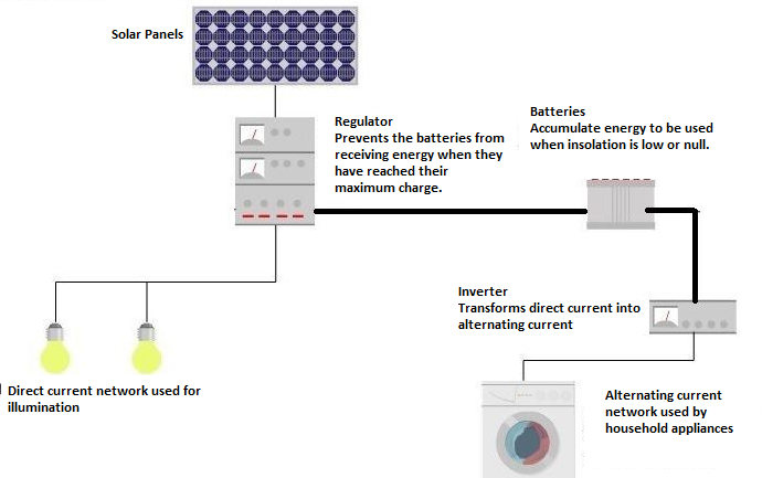
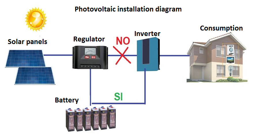
EYE! In real practice, the solar inverter is always connected to the output of the batteries , NEVER to the regulator, the inverter being in charge of controlling that they are not discharged excessively and the regulator only controls the charge of the batteries.
Photovoltaic installation
In theory, the charge regulator or controller could work in two different areas, in the charging area, its mission being to guarantee sufficient battery charge avoiding overloads , and in the discharge area, ensuring sufficient daily electricity supply and avoiding discharges beyond the depth of discharge of the battery .
But as we have already seen, the discharge area is not carried out by the regulator .
The dimensioning of the ISFTV photovoltaic solar installations is carried out in such a way as to ensure the supply of energy in the worst light conditions, for this reason the values in winter are taken as values.
This can cause that in summer the energy provided by the photovoltaic modules is almost double the estimated calculations, so the regulator between the panels and the battery is essential to avoid having an excess charge and / or current. This excess current could even boil the liquid in the batteries.
EYE!!! In installations connected to the Network without Batteries, the Charge Regulator is NOT necessary , since there are no batteries.
Why Doesn’t the Inverter Connect to the Regulator?
The regulator at its output can be connected to the inverter (if it has DC output terminals), but in these cases it must be taken into account that the regulator must bear the load of the total power of the electrical supply of the receivers in alternating mode, that is In other words, the maximum intensity that the regulator supports must be the same that the inverter supports, and that of the latter is usually very large.
Problem: we have to buy a very expensive regulator or it may not even exist for such a high intensity.
Only in the cases of low power AC installations is it recommended to connect the inverter directly to the regulator or when the consumption intensity is equal to or less than the load from the solar panels.
Let’s take an example to understand it better. A stand-alone installation with connection of the inverter to the regulator instead of to the batteries.
If we have a 30A regulator and the panels only charge 15, if you only consumed 15 amps, you would draw them directly from the panels going through the regulator and then to the inverter without going through the batteries. All right.
If we now have a consumption of 30A, the maximum that the regulator allows without burning, it means that 15 come from the panels and the other 15 from the battery. At the output of the regulator we have 30 amps that would go to the inverter. All right.
So far everything is correct and it seems that it makes sense, since we charge and discharge the batteries less, which would increase their duration. But….
If we are using an inverter of 1,000 Wts. at 12 V it means that at any given moment you can consume 1000/12 = 83.33 amps and that intensity cannot be removed from the regulator, since when trying it it would pluff, it would burn.
This is what usually always happens, that the intensity that the inverter can withstand is much greater than that of the regulator.
The solution would be to put a regulator with the same intensity as the inverter, but as this intensity is much greater, the problem is that either there are no such large regulators on the market or they would be very expensive.
Correct Solution : Inverter connected to battery. In this case the regulator only has to withstand the maximum intensity of the solar panels .
The problem of controlling excessive battery discharge is solved with inverters that carry the so-called ” low battery voltage protection ” which what it does is that when the batteries drop their voltage at terminals below a limit, the inverter cuts the power. supply of the batteries so as not to deplete them until this voltage threshold is exceeded.
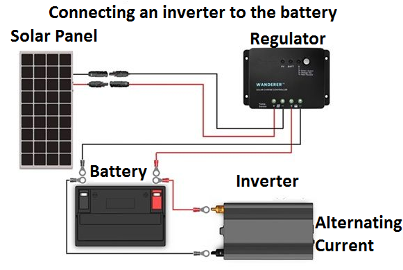
VERY important EYE !!! Protection fuses must always be placed between the battery and the inverter to protect the inverter in case of overcurrent. Better that the fuses are blown than the inverter which is much more expensive. We really should put them in all cases, this connected to where the inverter is connected.
Another alternative, increasingly used in installations with a lot of power, is to use an inverter that incorporates the regulator inside it, called Inverters / Regulators . This alternative will reduce wiring costs and system losses, as well as saving space.
All regulators usually have a direct current output called or used as a “charger”, so that the excess charge of the panels can be used for a small light bulb or direct current appliance, or even to recharge small electronic devices in DC. EYE do not connect the inverter here, as we already saw with the battery.
The only exception to the need for a regulator in an ISFTV is when the charging source (modules) produce much less power than the full battery charge. If a PV module produces 1.5% of the battery’s ampacity (amps) or less, then no charge controller is needed. Which is not usually frequent due to the expense of such a large battery.
Regulator Functions
The regulator is an electronic voltage and / or current regulating device that fulfills 3 essential functions:
– Protect the accumulator battery against overcharging or deep discharge . In the event that the battery is fully charged, the regulator interrupts the connection with the panels to avoid overcharging the batteries. Conversely, when its load falls below a certain percentage (depth of discharge or DOD), it cuts the connection with the consumer network to prevent it from being discharged below the depth of discharge marked in the installation design.
Protect the accumulator battery against overvoltages . At the input of the batteries, overvoltages can occur, for example when the working temperature of the solar cells drops a lot. The regulator protects the batteries from these surges that could damage them. In addition, solar modules usually have higher nominal voltages than batteries to ensure the correct charge of the battery.
– Avoid night-time discharge of batteries on photovoltaic generators. The regulator detects that it is night by measuring the input voltage of the photovoltaic modules. When it detects that it is night, it disconnects the input to prevent the circulation of current from the battery to the photovoltaic panels. As a basic solution, use a diode which prevents reverse current flow.
Other regulators, depending on the manufacturer, can protect us against short circuits, measure the temperature of the batteries, etc.
Calculation or Sizing of the Charge Regulator for an ISFTV
First case. Regulator to Batteries and Inverter connected to Batteries as well.
The charge regulators are determined by the maximum intensity of work (charge and discharge) and by the voltage in which we have designed our installation. The intensity of work will be the intensity of input or coming from the solar panels.
We need a regulator that is capable of regulating the maximum intensity that can come from the photovoltaic panels of the installation. This intensity will be taken from the short circuit intensity of the panels (the maximum that each panel can give).
We must first see in the used panels what is the short-circuit current (Isc). Imagine that we use two Schuco MPE 220 Solar Panel solar panels with the following characteristics.
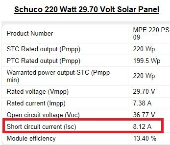
The short-circuit current (Isc) is considered to be the worst possible situation. As you can see, the chosen panels have a short-circuit current of 8.12A.
As we must already know the modules that we connect in parallel in the installation, their intensities will be added to give us the total intensity of the installation. The strings or branches of panels in series are connected in the DC connection box in parallel, and these branches are the ones that each one gives us the Isc of a single panel. In series the voltages are added but the intensities are the same. In parallel, the voltages are the same but the intensities are added.
Suppose we have two modules in parallel, then the total short-circuit current would be 8.12 x 2 = 16.24A. To be sure and not have problems, it is recommended to multiply the result by a factor of safety of 1.25.
The formula would be:
Regulator input current = Isc of each module x Number of branches in parallel x Safety factor .
In our case: 8.12 Amp x 2 x 1.25 = 20.3 Amps (minimum input current of the regulator).
This is the maximum intensity that the photovoltaic panels will give us . The output intensity to the battery will always be equal to or less than this, since it is the maximum that the panels can generate to charge the battery.
For this reason, normally the charging intensity (the one that comes from the panels) and the consumption intensity (the one sent to the receivers) are usually the same in most solar charge controllers.
If we connect the regulator to the inverter, the output intensity would be the one that would give us the result of dividing the inverter power by the direct voltage. It is not the case.
For our example, we must choose a regulator that has this input or load current equal to or greater than 20.3A.
If we do not have the data of the short-circuit intensity of the panel, we could do it by adding the power of all the panels of the installation and dividing it by the working voltage (that of the battery).
Remember that Power = Voltage x Intensity. It’s about clearing the intensity.
In our example the modules have a maximum power of 220Wp (peak watts). By having 2 in parallel the total sum of the powers is 440w.
If you look at the characteristics of the modules, the voltage at maximum power (Vmpp) is 29.70V, which means that the battery will work at 24V. Remember, the voltage at maximum power of the panels is always a little higher than that of the battery.
If the voltage at maximum power is 29V we use 24V batteries, if the Vmpp were 14V we would use a 12V battery.
If we divide 440 by this 24V voltage, we get an intensity of 18.33A. When multiplied by the safety factor (1.15) we have an input intensity of 21A. We would choose the regulator with the input intensity equal to or greater than 21A . As you can see, the result is more or less the same as before.
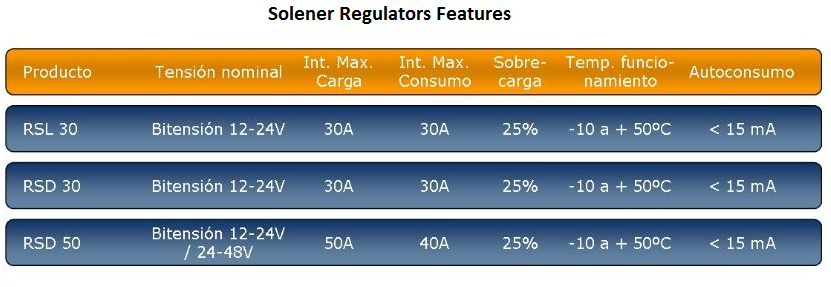
As the battery is 24V, the regulator must also be 24V , always of the same voltage as the battery. From the following table of regulators we could use any one.
The load intensity and the consumption intensity will be the same as it is not connected to the inverter.
Many regulators are dual voltage (look at the ones in the image above), being able to work both at 12V and 24V just by changing the position of a switch. They also usually support 25% overloads and the charge and discharge intensity is the same.
Remember that fuses must be placed between the battery and the inverter to protect the inverter in the event of an overload so that it does not burn out.
Self-consumption is the intensity that the regulator itself needs for its operation, in many cases it is not taken into account.
Important : Normally, what must be done for an adequate control of the battery charge is to choose the batteries to which the regulator is connected on the regulator’s own display and he would only be in charge of putting all the data correctly so that the ISFTV work perfect.
In the most advanced models of regulators you can define the minimum voltage level of the batteries manually and to the value that you want, but it is more advisable to choose the type of batteries and that it is the regulator itself that chooses it.
2nd Case: Regulator Connected to the Inverter-NOT RECOMMENDED
This type of connection is only recommended for installations whose final receivers do not have much power or when the load intensity and the consumption intensity are very similar. But …. Why make this type of connection?
The inverter connected to the regulator, in hours of the day when there is good generation and if the batteries are already dead, we can feed a moderate consumption without touching the batteries, that is, directly from the panels, which does not happen if we connect the inverter to the terminals of the drums.
Now be careful, if the user demands a lot of power at a certain time, the panels could give it and help the batteries, with which the inverter could consume some current peaks that the regulator does not support if we calculate it for the intensity of the panels as in the previous case.
In these cases, what we have to do is calculate the load intensity in the same way as we did previously, but now we must also calculate the consumption intensity in the following way: We must divide the expected power of all the receivers of the installation and divide it between the tension. It would be necessary to take the intensity of the IGA of the alternating installation , which is the maximum that will allow it to demand the inverter and therefore the regulator.
Imagine that in the previous example we have a sum of powers in receivers (washing machine, refrigerator, lamps, etc.) of 300w. If the battery voltage is 24V we have a consumption or output intensity of 300/24 = 12.5A. The regulator should have an output current or consumption greater than 12.5 A. In this case we could connect the regulator with the inverter.
It could be the case that the expected power was much higher, imagine that the consumption intensity was 60A in the IGA, this would make us have to buy a much more expensive regulator, and it is not efficient. In this case the inverter to the battery. In addition, the installation of panels means that it would be undersized.
Remember also that there are investors that have the regulator incorporated. In addition, investors if we connect them to the battery there is no problem because they have protection against excess battery discharge as the regulator for the desired depth of discharge.
What happens if the intensity of consumption and load are very large and I cannot find a Regulator for that intensity?
The solution would be to divide the total number of panels into two parts and use 2 regulators , each one for the intensity of each part of the panels. It is like doing 2 separate installations to later join them in the battery.
Once we know the characteristics of our regulator, we only have to choose what type it will be.
Regulators Types
The regulator controls the state of the battery by measuring the voltage at the terminals of said battery. From this voltage the charge and discharge control is developed, connecting or disconnecting the photovoltaic generator.
Depending on how the battery charge is regulated, the regulators are classified: –
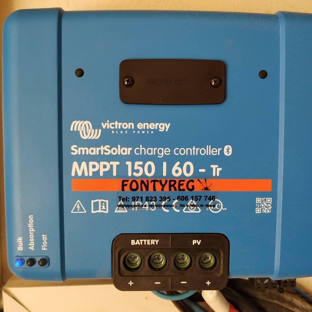
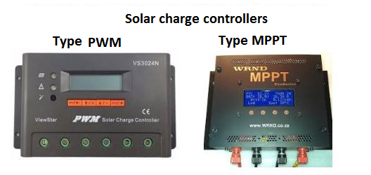
MPPT regulators or maximizer
The acronym MPPT (Maximum Power Point Tracking) stands for: maximum power point tracker. The “point” referred to is the one that corresponds to the optimal values for the output voltage and current that provide the maximum output power .
This type of control incorporates a current limiter, so as not to exceed the maximum current tolerated by the batteries when the input power transiently rises. An MPPT regulator modulates the panel voltage and adapts it to the characteristics of the connected batteries. They are the regulators used today in almost all ISFTVs.
They are more expensive than those that we will see below but they achieve an increase in energy production of 30% compared to PWM.
– PWM or conventional regulators
Also called All or Nothing. They were the first charge regulators that appeared on the market and performed the battery charge control according to an “all-nothing” system by switching electromechanical elements (relays), and could be called single-stage regulators.
The regulator allowed the passage of all the current available in the photovoltaic (PV) generator until the voltage in the battery reached a predetermined value (more or less at 14.5 V it is considered full). At this value the flow of current was interrupted. For values lower than 12V in the battery, it would re-establish the passage of all the current to the batteries from the PV generators
PWM charge controllers are less expensive (than MPPT) and are an ideal solution for smaller PV systems where price can be a critical point or where maximum efficiency and additional power are not really necessary.
PWM charge controllers are less expensive (than MPPT) and are an ideal solution for smaller PV systems where price can be a critical point or where maximum efficiency and additional power are not really necessary.
We will only use PWM regulators in the case of installations whose panels supply a power of less than 200w. For the rest always MPPT regulators.
If we refer to the way of switching with the battery (internal connection in the regulator to join panels to the battery) , we find two types of regulation systems:
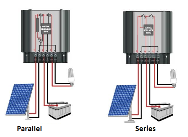
– Series Regulators , which incorporate electromechanical or electronic switches, which disconnect the generator when the voltage exceeds a certain reference level. During the night, the charging circuit remains open, preventing the batteries from discharging in the photovoltaic panel. It is used by almost all installations today .
– Regulators in Parallel , where the excess voltage is controlled by diverting the current to a circuit that dissipates the excess energy. In the image you can see R as the resistance from where the excess current is derived. Parallel type regulators must dissipate all the output current from the panel when the battery system reaches the state of full charge.
It creates power losses and reduces the maximum value of the charging voltage. This makes the parallel controls less efficient than the serial version and they are deprecated today . In parallel they are only used for small power installations .
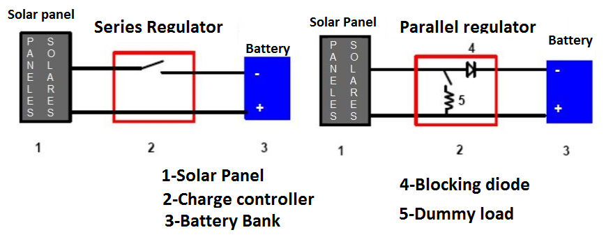
Conclusion: We will choose Series regulators of the MPPT type that have load intensity equal to the sum of the short-circuit currents of the parallel branches of the panels in the installation .
Connection and Disconnection of the Regulator to the Installation
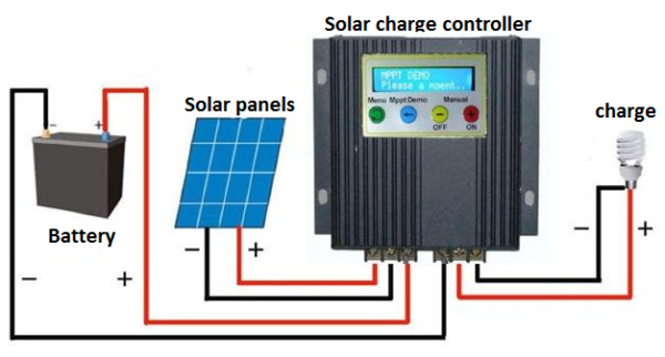
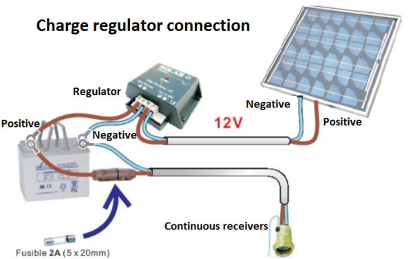
NOTE the steps for connecting a regulator to an ISFTV should always follow the following order:
1. connect the battery to the regulator – positive and negative
2. connect the solar module to the regulator – positive and negative
3. connect the load to the regulator – positive and negative
In case of uninstallation, proceed in reverse order!
Automatic reset to 12V / 24V dual voltage systems will not work properly if the connection order is not correct. This can damage the battery!